| Production enforce standard | ||||||||||
| Design and Manutacture | Face to face | Flange Dimension | Butt welding | Inspection and test | ||||||
| ANSIÂ B16.34/BS1873 | ANSIÂ B16.10 | ANSIÂ B16.5 | ANSIÂ B16.25 | APIÂ 598 | ||||||
| Chief property and specification | |||||||
| Normal Pressure | Shell test | Water seal test | Air seal test | ||||
| LB | Mpa | Lbf/in² | Mpa | Lbf/in² | Mpa | Lbf/in² | |
| 150 | 3.1 | 450 | 2.2 | 315 | 0.5-0.7 | 60-100 | |
| 300 | 7.8 | 1125 | 5.6 | 815 | |||
| 600 | 15.3 | 2225 | 11.2 | 1630 | |||
| 900 | 23.1 | 3350 | 16.8 | 2440 | |||
| 1500 | 38.4 | 5575 | 28.1 | 4080 | |||
| 2500 | 64.6 | 9367 | 47.4 | 6873 | |||
| Material for main parts | ||||||||||
| Body/Cover/Disc | Stem | Sealing Face | Sealing shim | Packing | Suitable medium | |||||
| WCB | 2 CR13 | 13Cr STL with body material  PTFE Nylon |
13Cr/Enhanced Flexible 1Cr13 /Flexible graphite  SFB-208 Soft steel F304 F316 F304L F316L |
Flexible graphite Enhanced Flexible graphite  SFB /260SFP/ 260PTFE |
Water Steam Petroleum Products |
|||||
| WC1 | 38CrMoAl 25Cr2Mov |
|||||||||
| WC6 | ||||||||||
| WC9 | ||||||||||
| C5Â C12 | ||||||||||
| CF8 | F304 | Nitric acid Aceic acid |
||||||||
| CF3 | F316 | |||||||||
| CF8M | F304L | |||||||||
| CF3M | F316L | |||||||||
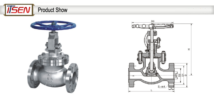
| Main external and connection dimension | ||||||||||
| Size | L | D | D1 | D2 | b | n-d | W | H | WT(kg) | |
| 150LB | Â | Â | Â | Â | Â | Â | Â | Â | Â | Â |
| 1/2" | mm | 108 | 90 | 60.5 | 35 | 12 | 4-15 | 125 | 169 | 3.8 |
| in | 4.25 | 3.5 | 2.38 | 1.38 | 0.47 | 4-0.59 | 4.92 | 6.65 | ||
| 3/4" | mm | 117 | 98 | 70 | 43 | 12 | 4-15 | 125 | 180 | 4.2 |
| in | 4.61 | 3.86 | 2.76 | 1.639 | 0.47 | 4-0.59 | 4.92 | 7.08 | ||
| 1" | mm | 127 | 108 | 79.5 | 51 | 12 | 4-15 | 125 | 190 | 8 |
| in | 5 | 4.25 | 3.13 | 2 | 0.47 | 4-0.59 | 4.92 | 7.48 | ||
| 1Â 1/2" | mm | 165 | 127 | 98.5 | 73 | 14.3 | 4-16 | 180 | 347 | 13 |
| in | 6.5 | 5 | 3.88 | 2.87 | 0.56 | 4-0.62 | 7.09 | 13.66 | ||
| 2" | mm | 203 | 152 | 120.5 | 92 | 15.9 | 4-19 | 180 | 356 | 21 |
| in | 8 | 6 | 4.75 | 3.62 | 0.625 | 4-0.75 | 7.09 | 14 | ||
| 2Â 1/2" | mm | 216 | 178 | 139.5 | 105 | 17.5 | 4-19 | 240 | 381 | 30 |
| in | 8.5 | 7 | 5.5 | 4.12 | 0.69 | 4-0.75 | 9.45 | 15 | ||
| 3" | mm | 241 | 190 | 152.4 | 127High Temperature Printing And Dyeing Pump The main flow components of the high temperature printing and dyeing pump are the suction chamber, the impeller and the pressurized water chamber. The water suction chamber is located in front of the water inlet of the impeller, and plays the role of guiding the liquid to the impeller; the water pressure chamber mainly has three forms: a spiral pressure water chamber (volute type), a guide vane and a space guide vane; the impeller is the most important part of the pump. The important working element is the heart of the flow passage part, and the impeller consists of a cover plate and a middle blade. Before the high-temperature printing and dyeing pump works, first fill the pump with liquid, then start the high-temperature printing and dyeing pump, the impeller rotates rapidly, and the blades of the impeller drive the liquid to rotate. , in this process, the liquid in the impeller flows around the blades, and the liquid acts a lift force on the blades during the flow movement, and in turn, the blades act on the liquid with a force equal to and opposite to the lift force, and this force acts on the liquid. Do work, so that the liquid gets energy and flows out of the impeller, at this time, the kinetic energy and pressure energy of the liquid increase. High Temperature Printing And Dyeing Pump,High Temp Pump,High Temperature Pump,Print And Dye Pump Jiangsu Qiantu Trading Co., Ltd. , https://www.jsqtpumptrade.com | |||||