Due to the complexity of the transient state of the processing state, it is often difficult to perform an accurate theoretical calculation of the structural stiffness. The designer can only calculate the stiffness of some components (such as shafts, screws, etc.) by calculations. The bending and torsional deformation of the bed, column, table, box, etc., and contact deformation of the joint surface are only It can be simplified and approximated. The calculation result is often very different from the actual one, so it can only be used as a reference for qualitative analysis. In recent years, although the finite element method is used in the design of machine tool structures for analysis and calculation, in general, it is still necessary to test, analyze, and compare models, objects, or similar prototypes at the time of design to determine a reasonable structural scheme. According to the following principles and measures, the structural rigidity of the machine tool can still be reasonably improved.
(1) Correctly select the shape and size of the section
After the components are subjected to bending and torsional loads, the magnitude of their deformation depends on the bending and torsional moments of inertia of the section, and their stiffness is high when the bending and torsion moments of inertia are large. Table 7-1 shows the moment of inertia of the cross-section shapes when the cross-sectional area is the same (ie, gravity is the same). From the data in the table, it can be seen that: when the same cross section is maintained, the wall thickness should be reduced and the section size of the cross section should be increased. The torsional rigidity of the circular cross section is larger than that of the square section, and the bending stiffness is It is smaller than the square section; the stiffness of the closed section is much larger than the stiffness of the unsealed section; the hole in the wall will reduce the rigidity, and the flange is added to the hole to make the bending stiffness recover.
(2) Reasonable selection and arrangement of partitions and ribs
The rational arrangement of the partitions and ribs of the support can increase the static and dynamic stiffness of the components. The structures of several columns shown in Figure 7.1 are longitudinal, transverse and diagonal ribs arranged inside. The results of the static and dynamic stiffness tests on them are given in Table 7-2. Among them, cross ribs (No. 5) play the best role.
For some thin-walled members, in order to reduce wall warping and distortion of the cross-section of the member, ribs as shown in FIG. 7-2 may be provided on the wall plate, preferably with honeycomb-like ribs. In addition to improving the stiffness of the component, it also reduces the shrinkage stress during casting.
(3) Improve the local stiffness of components
The coupling parts of the guide rails and support members of the machine tool are often the weakest part of the local stiffness, but the connection method has a great influence on the local stiffness. Fig. 7.3 shows several forms of coupling between the guide rail and the bed. If the guide rail is of a wide size, a double-wall connection type is used, as shown in (d), (e), (f). When the guide rail is narrow, a single-walled or thickened single wall connection may be used, or vertical ribs may be added to a single wall to increase the local stiffness.
(4) Selection of welded structure components
Supporting parts such as machine bed and pillar are welded by steel plate and section steel, which has the obvious advantage of reducing the mass and increasing the rigidity. The modulus of elasticity of steel is approximately twice that of cast iron. Under the premise of the same shape and contour size, if the rigidity of the welded part and the casting is required to be the same, the wall thickness of the welded part is only half that of the casting; if the local stiffness is required to be the same, Because the local stiffness is proportional to the cubic of the wall thickness, the wall thickness of the welded part is only about 80% of the wall thickness of the casting. In addition, whether it is the same stiffness to reduce the quality, or the same quality to increase the stiffness, can increase the resonant frequency of the components, so that the resonance is not easy to occur. The use of steel plate welding makes it possible to make the component a fully closed box-like structure, which helps to increase the rigidity of the component.
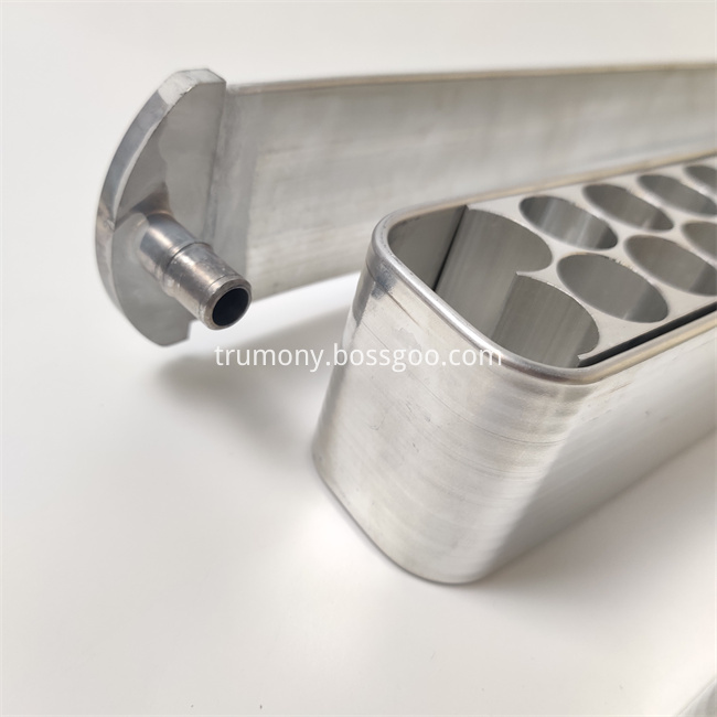
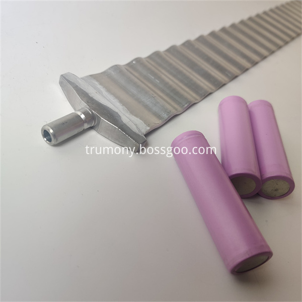
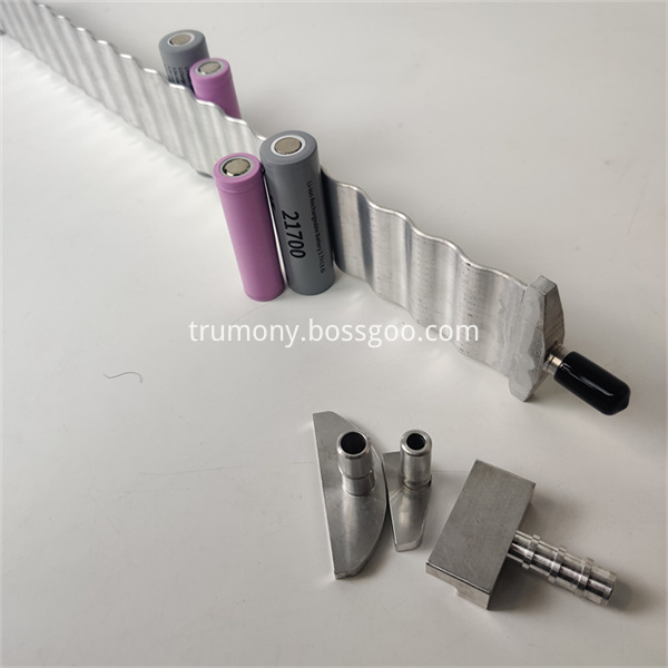
Cooling ribbon, also known as water cooling tube and water cooling plate, which is widely used in heat exchanging industry, such as battery cooling of new energy vehicles, energy storing device,5G parts cooling etc.
There are three main types according to processing technology:extrusion type, brazing type and blowing type.
Brazing type is widely used and have good heat exchanging at present. The maximum size of brazing cooling ribbon can be 1.8 meters, in addition, we have our own R & D team and CNC center. There are many ready and mature solution of heat exchanging.


water cooling ribbon,cooling ribbon for ev,cooling ribbon for battery pack
Trumony Aluminum Limited , https://www.szaluminumtube.com