With the rapid development of the industrial economy, a large number of DC equipment, variable frequency speed control equipment and other non-linear loads are widely used, and more and more harmonic currents are injected into the power grid. The generation of higher harmonics increases the harmonic loss of power and reduces the power factor of the system; it has great harm to the power network, it not only affects the quality of the power grid, but also has a great impact on the reliability of the power grid. Caused the relay protection to malfunction, burned the microcomputer protection circuit board, digital energy meter and other microcomputer devices. This paper mainly discusses the harmonic control of a 400V power supply system in a cable factory, and theoretically calculates and discusses the reasonable choice of LC AC filter. 
1 Fault phenomenon The 400V power supply system of the cable factory is composed of two European-style box-type substations. The wiring scheme of each box is the same, but the load of each box is different.
Two European-style box-type substations were put into operation soon, and the failure of components in the reactive power compensation cabinet occurred in the No. 1 box. The damaged components are mainly capacitor contactors and fuses. The most serious burnout is the capacitive contactor. At that time, it was thought that one might be the loose contact of the capacitor head contactor, the contact resistance increased, the pile head connection heats up and burns the capacitor contactor, which causes the fuse on the upper side of the contactor to burn out; another possibility is the fuse The inrush current generated by the capacitor switching is not protected, causing the contactor to burn out, and the resulting flame then damages the fuse. Subsequently, the burnt components were replaced, and all the wiring pile heads were inspected, and the reactive power compensation cabinet was continuously put into operation after rectification.
The rectified reactive power compensation cabinet was used less than one month, and the component damage occurred again. The location and phenomenon of component damage are basically the same as the last time. This is a loose explanation of the pile head wiring.
2 Analysis of the causes of the failure of the two reactive power compensation cabinets all occurred in the No. 1 box change, and the No. 2 box became safe and sound. Comparing and analyzing the load of the box-type substation No.1 and No.2, it can be found that the load of the No. 2 box is basically the asynchronous motor and the office lighting load; and the load of the No. 1 box has three DC motors in addition to the asynchronous motor. They are 185kW, 55kW, and 30kW. In addition, there are a large number of heating devices that control temperature through thyristors.
When the two reactive power compensation cabinets failed, the cross-linked cable production line of the plant was running, that is, the DC motor and a considerable part of the heating equipment were hung on the low-voltage busbar of the No. 1 box. The heating circuit of the plant adopts a three-phase half-controlled bridge rectifier circuit, and the AC power supply is used to supply power to the DC motor. Due to the non-sinusoidal output waveform of the rectifier, the rectifier circuits of different phase numbers will generate harmonic currents with different characteristics. For example, the three-phase bridge type 6-phase pulsating rectifier circuit generates harmonic currents of mainly 6k±1 times (5, 7, 11, 13 times, etc.) as shown in Table 1.
Table 1 6- phase pulsating rectifier current harmonic theoretical data
Harmonic order n 1 5 7 11 13 17 19 23 25
Harmonic current /% 100 20 14.3 9.1 7.7 5.9 5.3 4.3 4.0 
Therefore, the cross-linked cable production line may generate harmonics for the No. 1 box to 400V system during production.
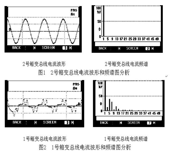
According to the calculation of the load nature and the theoretical formula, it can be determined that there is a harmonic current of 6k±1 times in the No. 1 box variable 400V system. In order to confirm and clarify the harmonic conditions and parameters of the No. 1 box-changing 400V system, multiple comparison measurements were made on the No. 1 and No. 2 box changes. The analysis of the No. 2 box change bus current waveform and spectrogram is shown in Figure 1. The No. 1 box change bus current waveform and spectrogram analysis are shown in Figure 2.
Comparing and analyzing Figure 1 and Figure 2, the No. 2 box variable bus current waveform is a regular sine wave. The spectrogram analysis also shows that the current basically contains only 50 Hz current of the fundamental wave; the No. 1 box variable bus current waveform is non-sinusoidal, spectrum analysis It can be seen that there are harmonics of 3, 5, 7, and 11 times. The total current distortion rate THDi is 52.32%, the power factor is 0.8, the system impedance is R = 0.1WL = 0.1mH, and the system short-circuit capacity is 10MVA.
The reason why the capacitor compensation device and the fuse are damaged several times in the case of the reactive power compensation cabinet of the No. 1 box is that the harmonic current generated by the cross-linked cable production line is amplified by the capacitor of the reactive power compensation cabinet, resulting in an overcurrent. Contactors and fuses are damaged by overheating.
3 Harmonic control Harmonic current not only affects the normal use of reactive power compensation cabinets, but also increases the reactive power electricity expenses, and also causes damage to other equipment such as electric motors in the same box. According to the requirements of GB/T 14549 "Power Quality - Utility Grid Harmonics", it is necessary to limit the harmonic voltage and harmonic current injected into the grid by various nonlinear loads.
The main measures to suppress and control harmonics in the power system are: increase the system short-circuit capacity; increase the supply voltage level; increase the pulsation number of the converter; improve the operation mode of the system, set the AC filter, etc. Harmonic components. For the cable plant, the only feasible and effective way to set up the power supply system is to set up an AC filter for harmonics control, while the filter can provide some or all of the reactive power to the system.
The AC filter is further divided into a passive filter and an active filter. An active filter is an active filtering device that injects a harmonic current into the system to cancel the harmonic current generated by the nonlinear load. It provides fast dynamic tracking compensation for varying harmonics and the compensation characteristics are unaffected by system impedance. The structure is relatively complicated, the running loss is large, and the equipment cost is high; while compensating harmonics, new harmonics are also injected. Passive filters (also known as LC filters) use the principle of LC resonance to artificially create a series resonant branch that provides a very low impedance path for the main harmonics to be filtered, so that it is not injected into the grid. The LC filter has a simple structure and obvious harmonic absorption effect; however, it only has a good compensation effect on the harmonics of the natural frequency; and the compensation characteristic is greatly affected by the impedance of the power grid. At a specific frequency, the impedance of the grid and the LC filter Parallel resonance or series resonance may occur between them.
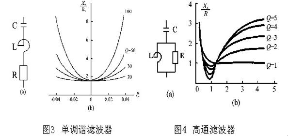
4 System constitutes LC filter is different according to the way of its capacitor and Reactor connection, the main commonly used are single-tuned filter and high-pass filter. Their structure and impedance characteristics are shown in Figures 3 and 4.

The cable factory's cross-linked cable production line is a production method that is fixed by sales, that is, a certain order is issued for production. According to the existing production statistics, since the cable produced is 35kV or higher, it is started twice a month for 2~5 days. From the results of several on-site measurements, the number of harmonics generated by the cross-linked cable production line is fixed, and the distortion rate (THDi) of each harmonic current fluctuates little.
According to the above measurement and analysis, it is decided to use a fixed series LC tuned filter in parallel with the busbar for harmonic control of the cable factory. When the cross-linked cable production line starts, the LC filter is put in, when the cross-linked cable production line is shut down. The LC filter exits; the capacitor capacity of the filter is used to compensate the reactive power required for the harmonic source of the cross-linked cable production line. The capacitor of the original reactive power compensation cabinet is reduced from 300mF to 180mF to meet the reactive power compensation requirements of other equipment. At the same time, the controller is replaced with a compensation controller with harmonic blocking function to cut off the capacitor when the harmonic distortion rate exceeds the limit. A single-tuned filter is used for the 3rd, 5th, and 7th harmonics, and a high-pass filter of 11 times is used for the harmonics of 9 or more times.
A series tuned filter is a capacitor used to filter out a certain harmonic by adding a reactor with XL = XC at the tuning frequency fn. The design steps for the series tuned filter for tuning the nth harmonic are: (1) Determine the capacitor capacity QC, and the capacitor reactive power should be balanced with the harmonic source reactive power and the reactive power of the system's existing reactive power compensation device. The total reactive power of the reactive power compensation device and filter is slightly lower than the total reactive power of the load.
(2) The reactance of the capacitor is XC = kU2/QC.
5 The effect of the calculation result of the control effect The cable factory harmonic control scheme consisting of components is used to control the harmonics of the No. 1 box. Subsequent field measurements show that the waveform of the total current of the No. 1 box is almost close to the sine wave, the voltage distortion rate THDu is 2.8%, the current distortion rate THDi is 6.6%, and the power factor is maintained at about 0.95.
In the cable plant's harmonic control scheme, the passive filter LC series filtering method with relatively low cost and suitable implementation is selected, and the harmonic current generated by the DC motor and the three-phase bridge type 6-phase pulsating rectifying device is selected. A good suppression effect has been achieved, in particular, the 5th and 7th harmonic currents with high harmonic content are eliminated.
Heat Transfer Oil Reactor,Quartz Tube Reactor,Outer Tube Reactor Electric,Outer Tube Disc Reaction Vessel
Wuxi Dingfeng pressure vessel Co., Ltd , https://www.wuxidingfeng.com