The physical medium layer is the basis of network communication, and the termination of network hardware interfaces is also the basis of physical layer connectivity. The failure rate accounts for over 80% of the entire network failure. Regardless of engineering construction or direct users, there are many misunderstandings and misunderstandings on the issue of cable termination. This article reviews the development process of related standards, combines test instruments and practical application of engineering, hoping to clarify some basic concepts and technologies. The problem helped.
When it comes to cable termination, frequently asked questions:
How to make a network cable connector? Termination using T568A or T568B? Is T568B higher in performance than T568A? Is T568B better compatible than T568A? Why can't the RJ45 plug be wired in order, but must the 3/6 line be connected across the 4/5 line? Why does the connectivity test pass but cannot connect to the network? How to choose connectivity test instrument?
Before answering the above question, we must also start from the "head":
One, RJ45 and RJ11
The RJ-45 is used as a twisted-pair Ethernet device interface, commonly known as the "Crystal Head." RJ-45 specifically refers to an 8-pin modular jack or plug as defined by IEC (60) 603-71. RJ is an abbreviation for "Registered Jack", which comes from Bell Corporation's Universal Service Ordering Codes (USOC) Universal Service Classification Code 2 and is controlled by the FCC (Federal Communications Commission, US Federal Communications Commission).

The RJ-11 usually refers to a 6-pin modular jack or plug, which is commonly used in the telephone network and is the generic name for the connector developed by Western Electric Co., which was issued on behalf of the U.S. government by the FCC (United States Federal Communications Commission). The RJ-11 is stipulated in one of the documents, but it is not standardized. There is no separate mention of the "RJ11" in the international standards. The RJ11 can be used as a 2-pin or 4-pin connector. Since the RJ11 is also used to call 4-pin modular connectors, it can easily cause confusion. Although RJ-11 is still in use, RJ-45 has a tendency to completely replace RJ-11.
Due to the mechanical size, the RJ-45 plug cannot be plugged into the RJ-11 jack, but in turn it is physically feasible, which leads to the misconception that the two should or can work together. In fact, the relevant standards support the compatibility of data and voice networks based on RJ-45 interface, but there is no evidence to support the cooperation and compatibility of RJ-11 and RJ-45 (see Section 4 “T568A/ B How to be compatible with the USOC section). Because RJ-11 is not standardized, its size, insertion force, insertion angle, etc. do not have a uniform design requirement, so interchangeability cannot be ensured, and even both can cause damage. For example: Since RJ-11 plug is larger than RJ-45 plug The hole is small and the plastic parts on both sides of the plug will damage the metal pins in the RJ-45 jack. It is recommended not to mix.
Second, what is T568
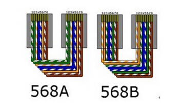
Referring to network cable termination, it involves T568A and T568B termination methods, also known as the wire map. The specific provisions of the two terminations were first seen in the US Communications Industry/Electronic Industry Association formally promulgated in June 2002. The TIA/EIA 568-B3 standard describes how four pairs of twisted pairs (8 cores) are arranged on the RJ-45 plug (Figure 2-1).
In the actual cabling project, the information outlets in the work area, the distribution frame, and jumpers connecting the computer and the information outlet can be arbitrarily selected to be terminated by one of them to form a “straight connection lineâ€. For the sake of specification, it is required that only the same kind of termination method can be used in the same project.
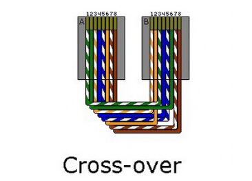
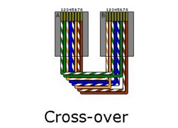
If a cable uses T568A on one end and T568B on the other (as shown in Figure 2-3), then a "crossover" is formed. This type of cable is used only when cascading between network devices, such as hubs and hubs. even. In addition, when connecting two PCs through a network port (not through a hub or switch), you also need to use a "crossover" connection. The fact that the "crossover line" is applied also serves as a counterevidence: that there must be two termination modes.
Since T568B was proposed in TIA/EIA568-B, TIA/EIA568-B (promulgated in February 2002) is a revised version of TIA/EIA568-A (promulgated in January 1994) and it is easy to create the illusion that : T568B appears later than T568A, T568B performance is higher than T568A. What is the actual situation?
Third, the origin of T568B
In 1985, when the computer network first began to develop, AT&T developed a new computer network based on an existing telephone system (based on the definition of the USOC to terminate the interface) and is downward compatible with it. The termination method used by AT&T was 258A. the way. The 258A termination method has been widely used in networks, especially in North America. As can be seen from Figure 3-1, it is the predecessor of T568B.
In the same period, many companies in the U.S. telecommunications industry required a third-party agency to harmonize the wiring standards, so the industry's regulatory agency, CCIA (Computer Communications Industry Association), went to the EIA (Electronics Industry Association). This requirement was put forward. It was not until July 1991 that the first draft standard, EIA/TIA-568, was enacted. A T568A termination method was proposed and a telephone system 4 supporting two pairs of twisted pairs downwardly compatible with a pair of twisted pairs was supported. After many revisions, the EIA/TIA-568A standard was formally promulgated in January 1994. After 10 amendments, TIA/EIA568-B was promulgated in 2002 and AT&T's 258A was renamed as T568B. T568A and T568B are also adopted by the international standard (ISO11801:2002) and become the universally accepted termination method.
It can be seen that the only difference between the A and B modes is that the positions of the orange line pair and the green line pair are interchanged. The purpose of using the color code is to allow the operator to easily identify the line pair. Electrical performance, there is no essential difference between A and B, nor You are better off. Due to the above historical reasons, the B method is earlier than the A method, which is why the T568B method is used more often. However, considering compatibility with the color code of the USOC, T568A tends to be the preferred choice for new installations, to support the dual-pair ISDN system upon arrival, and to support the purpose of high-speed data transmission. Because there is no difference in the continuity between A and B modes, there is no need to refit the system that has been installed in the B mode. Similarly, in a horizontally-wired system using the B-mode, using A-type jumpers to connect the terminals is also feasible and does not have any impact on the network performance.
It should be noted that T568A and T568B have become specific terminology for termination, and are referenced by ISO and various regional and national standards instead of the shorthand for TIA/EIA568-A and TIA/EIA568-B standard codes. Do not confuse the two. . After the issuance of TIA/EIA568-B, it completely replaced TIA/EIA568-A. Therefore, strictly speaking, TIA/EIA568-A should be called "T568A or T568B" instead of "T568A or T568B. "Because the so-called 568A standard has been repealed.
IV. Compatibility of T568A/B and USOC
The Universal Service Ordering Codes (USOC) have long been the most commonly used basic specifications for telephone systems. Although the same RJ-45 physical interfaces are used, the line-to-termination definition is different from that of the T568A/B. It does not support data and only supports voice transmission. (For the reason, see section ). In other words, T568A can be compatible with USOC regardless of the color standard or electrical. T568B is different from USOC color standard, but its electrical connectivity is compatible with 5, and vice versa.
In addition, after the two ends of the cable are terminated according to different regulations, the form of the cable is different. USOC specifies that the connection sequence of the connectors on both sides of the cable is symmetrical. Figure 4-1 shows that the two sides mirror each other. This is in contrast to the T568A. The situation of B is different.

If you straighten the two types of terminated cables, as shown in Figure 4-2 (metal contacts up, cleats down), it is easier to see the difference: the USOC line is straight, and the T568A/B is twisted in space 180 degrees.
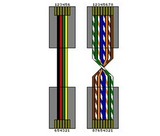
In short, on the premise that all RJ-45 connectors are used, traditional voice systems use 4/5 pairs, 10/100M Ethernet use 1/2, 3/6 pairs, and both can use 6 at the same time. Is compatibility. V. Transmission of electrical signals UTP (Unshielded Twisted Pair) channels currently using standard RJ-45 connectors have reached a bandwidth of 500 MHz (TIA/EIA6a/ISOEa) and can support a maximum transmission rate of 10 Gbit/s. The SFTP (thin metal mesh + screen braided double shielded twisted pair, such as ISOF class) link of the advanced connector (TERA/GG45/EC77) has a bandwidth of 600 MHz (the test cable has reached 1G-1.2GHz). Improvements in the cable production process have made it possible to increase the supporting bandwidth by a few tens of times, but its basic connections have not changed - each pair of cores is twisted with each other, transmitting a differential signal (this is also the "twisted pair" or "double" The origin of the name "strand". In the differential mode, the transmitted electromagnetic signals in the twisted pairs will cancel each other out (Figure 5-1). The interference to the outside is minimized, and the common mode interference from the external electromagnetic field is also effectively suppressed. In order to reduce the signal coupling, the 4 pairs of cores in the same sheath are different from each other in the length of 8 to further reduce the crosstalk between pairs.

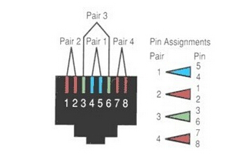
The standard termination of the color scale stipulates that it is convenient for human eyes to recognize, which not only considers the downward compatibility of the connector (4/5 line transmission voice), but also ensures that the differential signal can be transmitted in the twisted pair (3/6 data line Must cross over 4/5 sides). Observe the standard termination method (Figure 2-1, Figure 2-2). The dash and solid color patches appear at intervals, also to identify the line sequence more clearly. However, mistakes are still inevitable.
The faults in a single wiring diagram are divided into five types: open circuit, short circuit, reverse connection, wrong pairing, and string winding (also called bifurcation line pair, separation line pair, split line pair) (Figure 5-2). The combination of failures will actually be more complicated.
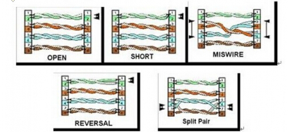
Among the above faults, the most difficult to be discovered is the "string-wound" fault, which destroys the twisting characteristics of the pair, and the differential signal is equivalent to the transmission in the parallel line (Figure 5-3) due to the twisted relationship of the original pair. , make crosstalk more serious.

As mentioned earlier, the RJ-45 termination method is not sequential, and the 4/5 and 3/6 pairs (see 1/2, 3/4, 5/6, 7/ 8 order). Due to the constant electrical continuity, only instruments with connectivity check for direct current cannot detect such failures. When used in a low-speed network, although the signal crosstalk is very large, sometimes communication can still be performed, and when the time passes, the user often suspects that the active device or software is faulty and cannot be immediately scheduled.
Fifth, check the winding failure
In addition to grasping the requirements of the termination standard, identifying the color scale, and carefully performing operations to avoid errors, the inspection string also depends on powerful instruments. These instruments generally have one of the following functions:
1. Measurement of Capacitance Analysis The line pair structure shows that twisted pairs of wires have much larger distributed capacitance than parallel wires of the same length and close to each other. Therefore, under the premise of correct conduction, as long as the measured capacitance of the four pairs is measured and compared with the expected value, it can be concluded whether there is a winding failure.
The measuring line pair distributed capacitance can be used to calculate the length of the pair (divided by the total capacitance of the pair divided by the capacitance of the unit length) in addition to the string failure, and can locate the breakpoint.
2. Measured impedance Similarly, after the line pair structure changes, its characteristic impedance also changes accordingly, according to which it can be judged whether there is stringing.
3, measure near-end crosstalk (NEXT)
Near-end crosstalk (NEXT) is the most basic electrical index for judging the transmission characteristics of cables. Correctly terminated but defective cables often result in deterioration of the near-end crosstalk index. There is a cable with a faulty winding and the near-end crosstalk indicator will be severely exceeded.
4. Measure the bit error rate The link with string failure sometimes can still access the network. Although the network speed is very slow due to near-end crosstalk, sending and receiving short data frames with the PING command does not reveal the problem. The use of a dedicated instrument for measuring the bit error rate can clearly see the difference in transmission performance, especially in the same network where the same hardware device is used, and it is easier to find the point of failure by performing a comparison test with the normal link.
When it comes to cable termination, frequently asked questions:
How to make a network cable connector? Termination using T568A or T568B? Is T568B higher in performance than T568A? Is T568B better compatible than T568A? Why can't the RJ45 plug be wired in order, but must the 3/6 line be connected across the 4/5 line? Why does the connectivity test pass but cannot connect to the network? How to choose connectivity test instrument?
Before answering the above question, we must also start from the "head":
One, RJ45 and RJ11
The RJ-45 is used as a twisted-pair Ethernet device interface, commonly known as the "Crystal Head." RJ-45 specifically refers to an 8-pin modular jack or plug as defined by IEC (60) 603-71. RJ is an abbreviation for "Registered Jack", which comes from Bell Corporation's Universal Service Ordering Codes (USOC) Universal Service Classification Code 2 and is controlled by the FCC (Federal Communications Commission, US Federal Communications Commission).

Figure 1-1 RJ-45 plug
The RJ-11 usually refers to a 6-pin modular jack or plug, which is commonly used in the telephone network and is the generic name for the connector developed by Western Electric Co., which was issued on behalf of the U.S. government by the FCC (United States Federal Communications Commission). The RJ-11 is stipulated in one of the documents, but it is not standardized. There is no separate mention of the "RJ11" in the international standards. The RJ11 can be used as a 2-pin or 4-pin connector. Since the RJ11 is also used to call 4-pin modular connectors, it can easily cause confusion. Although RJ-11 is still in use, RJ-45 has a tendency to completely replace RJ-11.
Due to the mechanical size, the RJ-45 plug cannot be plugged into the RJ-11 jack, but in turn it is physically feasible, which leads to the misconception that the two should or can work together. In fact, the relevant standards support the compatibility of data and voice networks based on RJ-45 interface, but there is no evidence to support the cooperation and compatibility of RJ-11 and RJ-45 (see Section 4 “T568A/ B How to be compatible with the USOC section). Because RJ-11 is not standardized, its size, insertion force, insertion angle, etc. do not have a uniform design requirement, so interchangeability cannot be ensured, and even both can cause damage. For example: Since RJ-11 plug is larger than RJ-45 plug The hole is small and the plastic parts on both sides of the plug will damage the metal pins in the RJ-45 jack. It is recommended not to mix.
Second, what is T568
Referring to network cable termination, it involves T568A and T568B termination methods, also known as the wire map. The specific provisions of the two terminations were first seen in the US Communications Industry/Electronic Industry Association formally promulgated in June 2002. The TIA/EIA 568-B3 standard describes how four pairs of twisted pairs (8 cores) are arranged on the RJ-45 plug (Figure 2-1).

Figure 2-1
In the actual cabling project, the information outlets in the work area, the distribution frame, and jumpers connecting the computer and the information outlet can be arbitrarily selected to be terminated by one of them to form a “straight connection lineâ€. For the sake of specification, it is required that only the same kind of termination method can be used in the same project.

Figure 2-2 Straight connection
If a cable uses T568A on one end and T568B on the other (as shown in Figure 2-3), then a "crossover" is formed. This type of cable is used only when cascading between network devices, such as hubs and hubs. even. In addition, when connecting two PCs through a network port (not through a hub or switch), you also need to use a "crossover" connection. The fact that the "crossover line" is applied also serves as a counterevidence: that there must be two termination modes.

Figure 2-3 Cross line
Since T568B was proposed in TIA/EIA568-B, TIA/EIA568-B (promulgated in February 2002) is a revised version of TIA/EIA568-A (promulgated in January 1994) and it is easy to create the illusion that : T568B appears later than T568A, T568B performance is higher than T568A. What is the actual situation?
Third, the origin of T568B
In 1985, when the computer network first began to develop, AT&T developed a new computer network based on an existing telephone system (based on the definition of the USOC to terminate the interface) and is downward compatible with it. The termination method used by AT&T was 258A. the way. The 258A termination method has been widely used in networks, especially in North America. As can be seen from Figure 3-1, it is the predecessor of T568B.

Figure 3-1 AT&T 258A Termination Method
In the same period, many companies in the U.S. telecommunications industry required a third-party agency to harmonize the wiring standards, so the industry's regulatory agency, CCIA (Computer Communications Industry Association), went to the EIA (Electronics Industry Association). This requirement was put forward. It was not until July 1991 that the first draft standard, EIA/TIA-568, was enacted. A T568A termination method was proposed and a telephone system 4 supporting two pairs of twisted pairs downwardly compatible with a pair of twisted pairs was supported. After many revisions, the EIA/TIA-568A standard was formally promulgated in January 1994. After 10 amendments, TIA/EIA568-B was promulgated in 2002 and AT&T's 258A was renamed as T568B. T568A and T568B are also adopted by the international standard (ISO11801:2002) and become the universally accepted termination method.
It can be seen that the only difference between the A and B modes is that the positions of the orange line pair and the green line pair are interchanged. The purpose of using the color code is to allow the operator to easily identify the line pair. Electrical performance, there is no essential difference between A and B, nor You are better off. Due to the above historical reasons, the B method is earlier than the A method, which is why the T568B method is used more often. However, considering compatibility with the color code of the USOC, T568A tends to be the preferred choice for new installations, to support the dual-pair ISDN system upon arrival, and to support the purpose of high-speed data transmission. Because there is no difference in the continuity between A and B modes, there is no need to refit the system that has been installed in the B mode. Similarly, in a horizontally-wired system using the B-mode, using A-type jumpers to connect the terminals is also feasible and does not have any impact on the network performance.
It should be noted that T568A and T568B have become specific terminology for termination, and are referenced by ISO and various regional and national standards instead of the shorthand for TIA/EIA568-A and TIA/EIA568-B standard codes. Do not confuse the two. . After the issuance of TIA/EIA568-B, it completely replaced TIA/EIA568-A. Therefore, strictly speaking, TIA/EIA568-A should be called "T568A or T568B" instead of "T568A or T568B. "Because the so-called 568A standard has been repealed.
IV. Compatibility of T568A/B and USOC
The Universal Service Ordering Codes (USOC) have long been the most commonly used basic specifications for telephone systems. Although the same RJ-45 physical interfaces are used, the line-to-termination definition is different from that of the T568A/B. It does not support data and only supports voice transmission. (For the reason, see section ). In other words, T568A can be compatible with USOC regardless of the color standard or electrical. T568B is different from USOC color standard, but its electrical connectivity is compatible with 5, and vice versa.
In addition, after the two ends of the cable are terminated according to different regulations, the form of the cable is different. USOC specifies that the connection sequence of the connectors on both sides of the cable is symmetrical. Figure 4-1 shows that the two sides mirror each other. This is in contrast to the T568A. The situation of B is different.

Figure 4-1 Correspondence between USOC Telephone Lines and Network Cables
If you straighten the two types of terminated cables, as shown in Figure 4-2 (metal contacts up, cleats down), it is easier to see the difference: the USOC line is straight, and the T568A/B is twisted in space 180 degrees.

Figure 4-2 Comparison of core arrangement of USOC and T568A
In short, on the premise that all RJ-45 connectors are used, traditional voice systems use 4/5 pairs, 10/100M Ethernet use 1/2, 3/6 pairs, and both can use 6 at the same time. Is compatibility. V. Transmission of electrical signals UTP (Unshielded Twisted Pair) channels currently using standard RJ-45 connectors have reached a bandwidth of 500 MHz (TIA/EIA6a/ISOEa) and can support a maximum transmission rate of 10 Gbit/s. The SFTP (thin metal mesh + screen braided double shielded twisted pair, such as ISOF class) link of the advanced connector (TERA/GG45/EC77) has a bandwidth of 600 MHz (the test cable has reached 1G-1.2GHz). Improvements in the cable production process have made it possible to increase the supporting bandwidth by a few tens of times, but its basic connections have not changed - each pair of cores is twisted with each other, transmitting a differential signal (this is also the "twisted pair" or "double" The origin of the name "strand". In the differential mode, the transmitted electromagnetic signals in the twisted pairs will cancel each other out (Figure 5-1). The interference to the outside is minimized, and the common mode interference from the external electromagnetic field is also effectively suppressed. In order to reduce the signal coupling, the 4 pairs of cores in the same sheath are different from each other in the length of 8 to further reduce the crosstalk between pairs.

Figure 5-1. The magnetic fields generated by the electrical signal on the twisted pairs cancel each other out
The standard termination of the color scale stipulates that it is convenient for human eyes to recognize, which not only considers the downward compatibility of the connector (4/5 line transmission voice), but also ensures that the differential signal can be transmitted in the twisted pair (3/6 data line Must cross over 4/5 sides). Observe the standard termination method (Figure 2-1, Figure 2-2). The dash and solid color patches appear at intervals, also to identify the line sequence more clearly. However, mistakes are still inevitable.
The faults in a single wiring diagram are divided into five types: open circuit, short circuit, reverse connection, wrong pairing, and string winding (also called bifurcation line pair, separation line pair, split line pair) (Figure 5-2). The combination of failures will actually be more complicated.

Figure 5-2 Wiring diagram Fault type
Among the above faults, the most difficult to be discovered is the "string-wound" fault, which destroys the twisting characteristics of the pair, and the differential signal is equivalent to the transmission in the parallel line (Figure 5-3) due to the twisted relationship of the original pair. , make crosstalk more serious.

Figure 5-3 String fault
As mentioned earlier, the RJ-45 termination method is not sequential, and the 4/5 and 3/6 pairs (see 1/2, 3/4, 5/6, 7/ 8 order). Due to the constant electrical continuity, only instruments with connectivity check for direct current cannot detect such failures. When used in a low-speed network, although the signal crosstalk is very large, sometimes communication can still be performed, and when the time passes, the user often suspects that the active device or software is faulty and cannot be immediately scheduled.
Fifth, check the winding failure
In addition to grasping the requirements of the termination standard, identifying the color scale, and carefully performing operations to avoid errors, the inspection string also depends on powerful instruments. These instruments generally have one of the following functions:
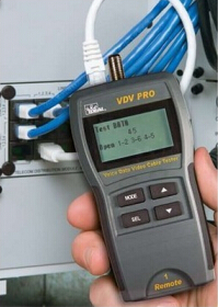
1. Measurement of Capacitance Analysis The line pair structure shows that twisted pairs of wires have much larger distributed capacitance than parallel wires of the same length and close to each other. Therefore, under the premise of correct conduction, as long as the measured capacitance of the four pairs is measured and compared with the expected value, it can be concluded whether there is a winding failure.

Figure 6-1 Typical full-featured (can test all wiring diagram faults) verification meter
The measuring line pair distributed capacitance can be used to calculate the length of the pair (divided by the total capacitance of the pair divided by the capacitance of the unit length) in addition to the string failure, and can locate the breakpoint.
2. Measured impedance Similarly, after the line pair structure changes, its characteristic impedance also changes accordingly, according to which it can be judged whether there is stringing.
3, measure near-end crosstalk (NEXT)
Near-end crosstalk (NEXT) is the most basic electrical index for judging the transmission characteristics of cables. Correctly terminated but defective cables often result in deterioration of the near-end crosstalk index. There is a cable with a faulty winding and the near-end crosstalk indicator will be severely exceeded.
4. Measure the bit error rate The link with string failure sometimes can still access the network. Although the network speed is very slow due to near-end crosstalk, sending and receiving short data frames with the PING command does not reveal the problem. The use of a dedicated instrument for measuring the bit error rate can clearly see the difference in transmission performance, especially in the same network where the same hardware device is used, and it is easier to find the point of failure by performing a comparison test with the normal link.
Double Girder Overhead Crane Kit With Hoist
Crane kits is now popular all over the world due to the sharply increased shipping costs.Whatever Overhead Crane , Gantry Crane or Suspension Crane,you can find Crane Kit in Eurocrane. Crane kit means all components except steel structure,you can also choose freely. Crane kits are supplied with hoisting unit,there are various type of hoisting unit,like low headroom rope Hoist ,Double Girder Hoist and etc.);end carriages (with connection plates); cable festoon system; control panel and pendant.
Double Girder Overhead Crane,Overhead Travelling Crane,Overhead Bridge Crane,Double Girder EOT Crane,Overhead Crane
EUROCRANE GLOBAL , https://www.craneparts.pl