Problem
The flow rate of tap water is measured by an electromagnetic flowmeter. Most of the time in a year is very accurate, but in the high temperature period, the minute table goes faster than the master meter.
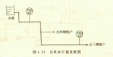
The 5th and 3rd floors of a podium in a building in Shanghai are equipped with a set of tap water flow meters. The fourth floor is not equipped with a meter. The difference method is used to calculate the water consumption:
Q4= Q5-Q3
Q4—the total amount of water consumed by users on the fourth floor, m3;
Q5—the total amount of total surface water on the fifth floor, m3;
Q3—The total amount of water consumed by users on the third floor, m3.
The system diagram is shown in the figure.
From the statistics of computer measurement data acquisition system, in the past few years, the total water consumption statistics are normal, but in the hottest days of Shanghai in the summer of 2010, Q4 has a negative value, the reason is Q3>Q5, this conclusion is wrong. of. 
Analysis and diagnosis
(1) Why is the indication value of the third floor electromagnetic flowmeter high?
The relevant personnel inspected the scene and found that the water tank located on the fifth floor had no direct sunlight, and the water was replenished by the water pipe network, and the water temperature was low. Since the water tank is an open container, the dissolved air in the water should have reached saturation. The water pipe absorbs heat from the atmosphere along the way, and the water temperature rises, especially on the third floor. There is a section of about 20m long laid outdoors, the temperature rises higher, and the tap water flows through the third floor flow meter. The gas is precipitated from the water and collects in the upper part of the horizontal pipe. When the pipeline reached the third floor, there was no chance of going up, so the gas accumulated in the horizontal pipe could not be discharged.
The tap water flowmeter installed on the horizontal pipe on the third floor also inevitably has gas, which occupies a certain flow cross-sectional area, so that the flow rate is high.
(2) Suggestions for rectification
A gas collector and an exhaust valve are added at appropriate positions on the horizontal pipe of the third floor, and the gas in the pipe is periodically discharged. In the autumn, winter and spring, there is no gas accumulation in the pipe, and generally no exhaust gas is required.
(1) Reasons for negative values ​​in Q4
There are two reasons for the negative value of Q4. One is the accumulation of gas in the horizontal pipe on the third floor, and it cannot be discharged by itself, and there is no exhaust port, so that the third floor tap water flow meter shows a high value; the second is in the formula (4.22). , Q4 is a small value, that is, the fourth floor is a
For very small users, the monthly statistics show that the water consumption is less than 2% of the third floor users, so the Q5 and Q3 errors are eventually digested by Q4, which will bring a big error to the fourth floor measurement data.
If the meter is modified on the fourth floor and the water consumption on the third floor is changed by the method of subtraction, there will be no negative user value. This lesson can be concluded that “measuring small†and “calculating big†is a useful experience.
(2) Install an exhaust valve where necessary
It is also an important experience to install an exhaust valve where it is possible to accumulate gas and not be able to discharge these gases by itself.
(3) Another type of non-full pipe flow measurement A object
The flow measurement objects such as municipal drainage and wastewater treatment are not completely filled, but they are completely different from the above.
The method of processing is also completely different.
For measuring objects that are often partially filled and cannot be filled into a full pipe, a non-full pipe flow meter should be used. The following is a type of non-full tube flow meter.
Non-full tube electromagnetic flow and the working principle of the meter
Pipeline water flow meters are commonly used for liquid full pipe flow in closed pipes. Pipeline water flow meters are not suitable for situations where the flow varies greatly, sometimes filled with piping, and sometimes filled with piping. At this time, a non-full pipe water flow meter is required.
The non-full-tube electromagnetic flow sensor can be operated in a wide range according to the installation pipe diameter, and can be used for measuring the full surface flow of closed pipes and free surface flow of non-closed pipes or open pipes without causing head loss, such as municipal Drainage, wastewater treatment, agricultural irrigation, fluid flow measurement by natural flow.
The tap water flow meter uses a constant cross-sectional area of ​​the sensor to measure the average flow rate to obtain a flow rate. The cross-sectional area of ​​the fluid in the non-full tube varies. The flow measurement not only measures the average flow rate through the sensor, but also the cross-sectional area of ​​the fluid flowing through the sensor. That is, the flow measurement of the non-full-tube tap water flow meter. At least two variables, flow rate and level, are required.
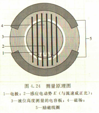
Figure 4.24 shows the structural principle of a non-full-tube flow sensor model TIDALFLUX4000. It is an electromagnetic flow sensor with an integrated capacitance level measurement system designed for conductive liquids. The flow rate q(t) flowing through the pipe is:
q(t)=v(t)A(t) 
Where v(t) - flow rate;
A (t) - the cross-sectional area of ​​the fluid.
The flow rate is determined based on the known principle of electromagnetic flow measurement. In order to reliably measure the liquid level of 10%, the two measuring electrodes are arranged at a height of about 10% of the lower part of the measuring tube. There is a pair of excitation coils on the upper and lower sides of the measuring tube, and a magnetic field is generated when the exciting current flows through the coil. The conductive fluid flows through the magnetic field through the insulating pipe to generate the induced electromotive force E:
E=vKBD
Where v is the average flow rate;
K—geometry correction factor;
B—magnetic induction strength;
D measures the inner diameter of the tube.
The induced electromotive force E is collected by the electrode, which is proportional to the average flow velocity v, which is proportional to the flow rate q. The induced electromotive force E is very small (typically 1W coil power, 1mV signal is obtained at v=3m/s), and then converted by signal The amplifier amplifies, filters, and converts to accumulate, record, and output signals.
In Figure 4.24, the fluid cross-sectional area A is calculated from the known measuring tube inner diameter and level measurement system, and the liquid level detecting electrode is placed in the measuring tube lining.
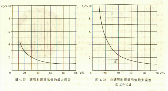
Compared to a full-tube tap water flow meter, the non-full-tube tap water flow meter has an additional level error, so the measurement accuracy is not as high as that of a full-tube type. In the curves shown in Figure 4.25 and Figure 4.26, it is assumed that the full scale value is at a flow rate of at least 1 m/s and is calibrated.
1 when the fluid is full of pipes
Er≤1%MV when av≥1m/s
When bv<1m/s, Er=o.5%MV+5 mm/s
c. Minimum liquid level: 10% of the inner diameter of the pipe
2 when the fluid part is full of pipes
Full flow rate ≥1m/s Er≤1%FS

Transmission Gasket,Oil Pan Gasket,Transmission Pan Gasket,Torque Converter Seal
HONG KONG CRS INTERNATIONAL TRADING COMPANY LIMITED , https://www.crstrans.com