The straight-in wire drawing machine adopts variable frequency speed control system with advanced technology and significant energy saving. The speed range is 30:1 during normal operation, and it can provide more than 1.5 times of rated torque at 5% of rated speed.
This article takes a straight wire drawing machine field of production wire as an example to illustrate the application process and effect of frequency conversion control.
Second, technology introduction and requirements
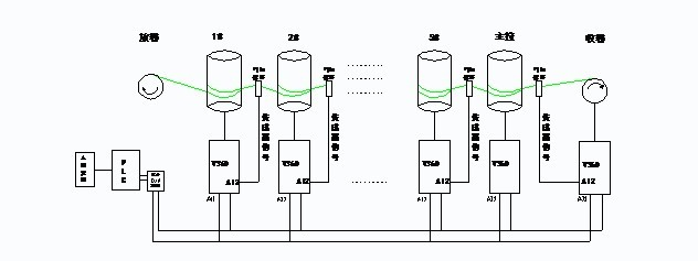
1. Each stage has a positive rotation and a reverse rotation function. 2. It has a front connection (the first station has no front connection), and a back connection function (there is no rear connection for the rewinding). 3. It has a mode hopping function (including the main pull). , And based on the mode-hopping situation, automatically calculate the system frequency ratio 4. The maximum speed of the system operation is 8m/s
5. The system has automatic metering and weighing functions, and has an automatic shutdown function when the meter is set and the weight is reached.
6. Acceleration and deceleration are stable, there is no big fluctuation 7. The system runs stably, and has the function of disconnection detection, alarm and shutdown. III. System scheme and debugging 1. System composition
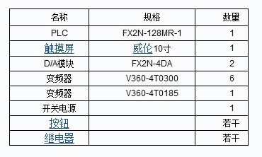
3. The logic of the system operation requires that there is only a logical relationship between the first station and the rewinding. In addition to the forward rotation and reverse reversal, the first station has a rear linkage function and the rewinding has a front linkage function. There are four logical relations from the second level to the main pull, which are the jog forward, the jog reverse, the front joint, and the rear joint. Examples are as follows:
3# Jog Forward: 3# Close Forward Jog Terminal 3# Jog Reverse: 3# Close Reverse Jog Terminal 3# Previous: 1# Run, 2# Run, 3# Run, and 3# For the host (speed given for PLC analog AI2 given, no pendulum feedback)
3# rear connection: 3# operation, 4# operation, 5# operation, 6# operation (host), 7# operation 4. Trip function In addition to rewinding, any one or more of the system can be skipped (However, the main pull and N-level slaves are reserved as at least one host.) When one or more hops are selected on the display unit, the system automatically calculates the speed ratio between the master and the remaining slaves. Send to frequency converter.
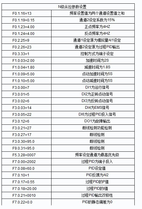
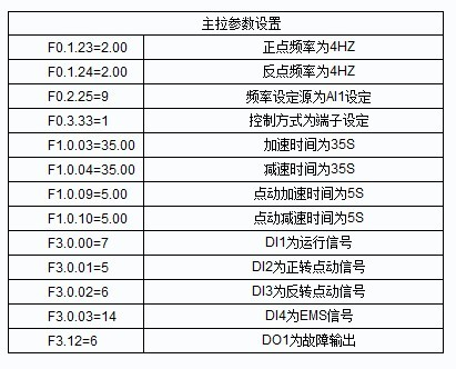
5. Debugging parameters
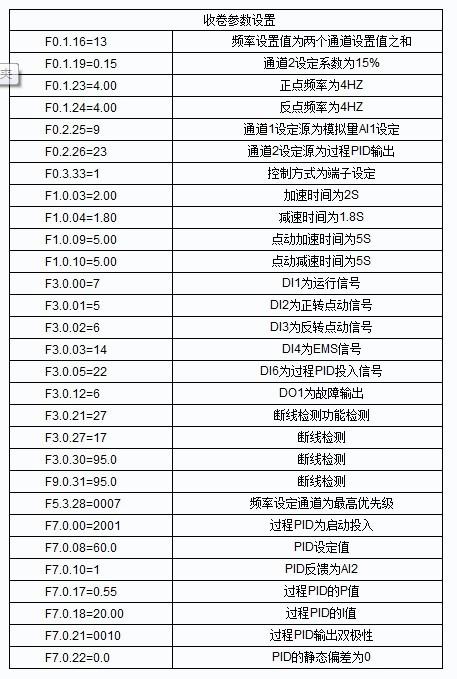
6. Commissioning steps Wiring with the following wiring diagram (partial screenshots)
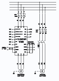
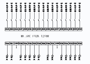
(2) After completing the motor parameter learning, set the parameters according to the above debugging parameters;
After the preparation of the above commissioning work is completed, the commissioning (3) adjusts the maximum and minimum values ​​of the cylinder rocker sensor. The larger the range, the higher the adjustment accuracy and the better the adjustment effect. Monitor the adjustment through D1.0.04. After the adjustment is completed, modify the corresponding AI2 corresponding minimum value [F4.0.02] and the maximum value [F4.0.03]
(4) After the calibration of the cylinder pendulum is completed, before the thread is not threaded, check the movement from the first station to the last station to see if the brake device and the pulley of each station are installed;
(5) Begin threading and debugging. When debugging, press the threading material in the order of one level down, the first level is adjusted and then the next level is adjusted, the first manual, then linkage, first low speed and then high speed;
(6) The most important debugging process is to debug the PID limiting ratio and the P value and I value of the PID. The experience of I value debugging is that the I value is greater than the acceleration and deceleration time of pulling and winding of N level, and is less than the acceleration and deceleration time of the main pull. If there is a loose line at the previous stage during the threading linkage process, the PID limit value at the previous stage is too small. Modify the value of [F0.0.19]. The limit value of the general system is 10%~20. Between the %; P value is too large to cause a large start swing swing, easily lead to shock damage to the mechanical limit, P value is generally between 0.3 ~ 0.8, gradually adjusted from small to large.
(7) After the low-speed threading is completed, test the functions before and after the joint (8) to complete the logic test, start the overall low-speed start, and then gradually increase the speed to adjust, after completing the start and stop multiple times, basically complete the entire system debugging .
Fourth, the debugging effect and summary of the use of Quartet high-performance vector drive V360 drive, after the optimization of system parameters, the system threading, start and stop very smooth, high-speed stable operation (8M/S operation), and greatly reduced the breakage and other failures. Compared with the DC drive system, the efficiency and power saving rate are also greatly improved. Moreover, the electrical configuration of the system is concise, clear logic, and easy to check for faults.
Crystal Roller Shutter Door Fast Commercial Door For Shopping Market
Automatic Rolling Shutter Door/rolling shutters for sliding glass door
Specifications
1) Quickly open&lclose
2) High quality, best price
3) Material: transparent PC
4) waterproof, UV protection,noise insulation
Motorized transparent PC commercial rolling door
Shuotian company specialized in high speed door, industrial door, commercial roller door &crystal rolling door, roller shutter
door, shop roller door. Crsytall roller door could widely use for commercial shop & shopping center.
Features: (Crystal roller door & Shop rollerr door)
--Almost transparent - display can be seen when shop is closed
--High security - near steel strength
--Virtually indestructible - Fabricated from extruded aluminum, robust weather and rust proof with polycarbonate glazing
making the shutter almost indestructible.
--Ideal for shopping malls and high profile shops
--Custom made - to fit every opening perfectly
--Electrically operated for fast easy roll up and roll down operation.
Curtain specification:
-- import high viscosity polycaronate material
-- Impact strength: 1400J/m2
-- Elongation at break: 250%
-- Transparency: 88%
-- Bending strength: 78 Mpa
-- Rockwell hardness(HRR): 60
crystal roller shutter door ,fast roller shutter door ,pc bulletproof plastic door
SHENZHEN HONGFA AUTOMATIC DOOR CO., LTD , http://www.hongfarrud.com