With the continuous improvement and development of control theory and the wide application of computer technology in the field of industrial control, the automation level and control quality of the control system have been significantly improved and improved. While pursuing good control performance of the control system, higher and higher requirements are also put forward for improving system reliability and maintainability. For thermal power plant thermal control process, the current method to improve the reliability of the control system is to improve the reliability of various components of the system and increase the hardware redundancy, but this will increase the cost and scale of the system. To this end, real-time fault diagnosis techniques can be used to establish a monitoring system that can quickly detect and isolate faults in the early stages of system failures or faults, and estimate the size of the faults, and then take necessary measures to prevent the faults from expanding. The purpose of improving system reliability and reducing maintenance time and cost [1]. In addition, the thermal power plant control system has many loops, and the control equipment (sensors and actuators, etc.) are widely distributed, and it is time-consuming and labour-intensive to rely on human power to check and find faults. According to statistics, the time spent looking for system failures accounts for about 90% of system repair time [2]. For this reason, this paper studies the fault diagnosis and implementation of the thermal control system in thermal power plants.
First, the composition of superheated steam temperature control system Superheated steam temperature control is a very important control system in the thermal control system, its main task is to maintain the superheater outlet temperature within the allowable range and protect the superheater, so that the wall temperature does not exceed Allow temperature. The temporary deviation of the superheated steam temperature must not exceed ±10°C, and the long-term deviation must not exceed ±5°C. Excessive temperatures will cause overheating of the superheater and the turbine high pressure cylinders to be damaged; lower temperatures will reduce the unit's thermal efficiency and affect economic operation [3]. The failure of the superheated steam temperature control system will bring serious consequences to the operation of the entire power plant. Therefore, the study of fault diagnosis using the superheated steam temperature control system is representative and practical.
Figure 1 shows the structure of superheated steam temperature control system for a 300MW unit in a thermal power plant. The control system adopts two-stage water injection method to reduce the temperature. The steam generated by the boiler steam drum is heated by the superheater of the ceiling and merges into a pipeline after the outlet box of the vertical low-temperature superheater. The B side enters the screen superheater. After the rear screen outlet header, the two pipes on the left and right sides are desuperheated by the secondary and secondary sprays and finally enter the final superheater [4].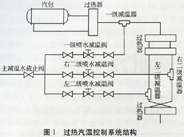
According to the need of fault diagnosis of the superheated steam temperature control system, important sensors and actuators included in the superheated steam temperature control system were sorted out. Among them, the sensors include: first-order superheater front, rear left and rear right temperature sensors, and front-end superheater Left, front right, rear left and right temperature sensors, left and right temperature sensors of the final superheater, first-level temperature-reducing water flow sensors, left secondary and right secondary desuperheating water flow sensors, etc.; actuators are: primary spray Water desuperheating valve, left secondary and right secondary sprinkler desuperheating valve, primary desuperheating water stop valve.
Second, the contents of the fault diagnosis study A typical control system structure shown in Figure 2. According to the division of each part of the control system, the objects of fault diagnosis include: (1) control objects, ie equipment body; (2) control system sensors; (3) control system actuators; (4) caused by changes in the control system state Failure [5]. Because the fault diagnosis of the equipment body is studied separately, the fault diagnosis of the control system studied in this paper only includes sensor fault diagnosis, actuator fault diagnosis and operating status diagnosis.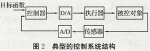
Combined with the structural features of the superheated steam temperature control system, the research contents of fault diagnosis are summarized as follows: (1) The fault diagnosis of important sensors in the superheated steam temperature control system is studied, including monitoring whether each temperature sensor and desuperheating water flow sensor is working properly. If there is a fault, an alarm display is performed and the fault sensor is separated; (2) The fault diagnosis of important actuators in the superheated steam temperature control system is studied, including monitoring of the operation status of each spray water temperature reducing control valve and each shutoff valve, and the fault is found Alarm and separate fault actuators in time; (3) Study the diagnosis of the system fault caused by the change of state of the superheated steam temperature control system, diagnose the cause of the fault and give the operation instructions.
Third, the superheated steam temperature control system common faults 3.1 sensor fault Superheated steam temperature control system common sensor faults include: gain, deviation, overspeed, pulse fault and so on.
(1) Sensor constant gain fault can be expressed as:
Where: uin(t), uout(t) are the input and output signals of the sensor, and ai is the proportional coefficient of constant gain variation.
(2) Sensor constant deviation fault can be expressed as: In the formula: Δi is the zero deviation of the sensor.
(3) Sensor disconnection fault can be expressed as:
Equation (3) shows that the sensor has no signal output.
(4) Sensor overspeed fault can be expressed as: Where: uout(t) is the rate of change of the sensor output signal; δmax is the maximum allowable rate of change of the sensor.
(5) Sensor pulse fault can be expressed as:
Where δ is the pulse signal superimposed on the sensor output signal.
3.2 Actuator faults Common actuator faults in superheated steam temperature control systems include: gain, offset, stuck, hysteresis, stick-slip, leakage fault, etc., where the description of gain and offset faults is the same as above, and other fault features are simplified. As follows.
(1) Actuator stuck failure can be expressed as:
Where ai is a constant. That is, the actuator output does not change with the input, but stabilizes at a fixed position.
(2) Hysteresis of the actuator can be expressed as: Where: Qk represents the flow when the actuator is open stroke; Qg represents the flow when the actuator closes the stroke; uout, k, uout, g are the actuator output corresponding to the opening stroke and the closing stroke respectively; λ is the difference between the two flows. value. The hysteresis failure means that the corresponding flow rate is different when the actuator's upper and lower stroke opening degrees are the same.
(3) Under normal conditions, the valve stem moves smoothly, but when viscous-sliding failure occurs, the valve stem action is "motion-stop-motion" movement, which is a kind of damage to the valve. The fault phenomenon is shown in Figure 3 [6].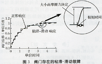 (4) Actuator leakage fault can be expressed as:
Q=λ(uout=0)(8)
Where: Q is the actuator-controlled flow; λ is a constant. That is, when the actuator valve is completely closed, there is still a flow signal.
Fault Diagnosis Theories and Methods Although there are many kinds of fault diagnosis theories and methods, they can be generalized into two categories [4,7]: (1) Diagnostic theories and methods based on mathematical models, such as fault detection filtering Instrumental methods, equivalent space equation methods, fault detection methods, etc.; (2) Non-model-based diagnostic theory and methods, such as multivariate statistical methods, neural network methods, expert system methods, or data analysis methods [7].
According to the author's research and combined with the characteristics of the thermal control system, the following diagnostic methods have high practical value in the fault diagnosis of the thermal control system.
(1) For some simple non-correlated faults in thermal control systems, simple, targeted methods such as signal analysis and redundancy analysis methods can be used. Although simple, these methods are easy to implement and can effectively diagnose such failures.
(2) Relatively complicated diagnostic methods need to be used for relatively complex faults that have a correlation. Because the thermal control system is not easy to establish an accurate mathematical model, it is difficult to achieve a good diagnostic effect in the application based on the mathematical model; and the statistical method does not depend on the mathematical model, it can find out in a large amount of historical real-time data Fault features and fault information are therefore a fault diagnosis method suitable for application in thermal control systems.
(3) Due to the inaccuracy of the statistical method and its own limitations, the accuracy of fault diagnosis is not high and fault separation is difficult. Therefore, it is an ideal solution to establish a comprehensive diagnosis method based on statistical methods and supplemented by mathematical model methods to achieve fault diagnosis of thermal control systems.
V. DIAGNOSIS EXAMPLE Diagnostic tests were conducted on failures, breaks, gains, deviations, overspeeds, etc., of the sensors in the superheated steam temperature control system of the thermal power plant, and failures of the actuators such as stuck, hysteresis, and stick-slip. The diagnostic methods used for troubleshooting are simple diagnostic methods for this type of failure. These methods are simple, reliable and have high diagnostic accuracy. After field testing, they have achieved good diagnostic results.
5.1 Disconnection fault of the left temperature sensor (K-type thermocouple) after the secondary superheater (1) Fault phenomenon As shown in Figure 4, the temperature signal suddenly jumps from 463.49°C to 25.45°C (thermocouple cold junction compensation temperature). The rate of change far exceeds the normal rate of change of the sensor. From the figure it is easy to see that a disconnection fault has occurred in the left temperature sensor after the secondary superheater.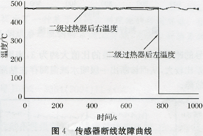 (2) Diagnostic methods determine whether or not the sensor has failed by calculating the rate of change and direction of change of the temperature sensor signal. This is because when the sensor breaks, the temperature signal changes from the normal negative moment to a relatively small value (thermocouple cold junction compensation temperature), and the rate of change is large. Therefore, if the rate of negative change of the temperature signal at a certain moment is calculated to exceed the maximum rate of change of the sensor itself, it is proved that there is a breakage fault [8].
(3) The diagnosis result is 463.49°C at a moment before the fault, the fault time is 25.45°C, and the diagnosis cycle is 1s. Therefore, the rate of change of the temperature signal at this moment is 438.04° C./s, which is far beyond the maximum allowable change rate of the temperature sensor, so that a breakage fault of the left temperature sensor after the secondary superheater is diagnosed at this time.
5.2 Primary spray water desuperheating valve stick-slip fault (1) Fault phenomenon It can be clearly seen from Figure 5 that the command signal changes smoothly, and the feedback signal has a step-like change, so the desuperheating valve has viscous-sliding failure produce.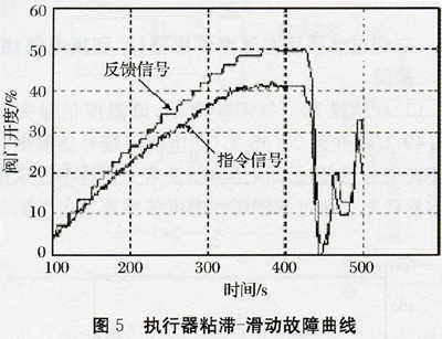 (2) Diagnostic methods The viscous-slip fault diagnosis can be performed based on the frequency distribution of the speed change events occurring in the viscous-sliding process of the valve stem. When the stem movement is smooth, the average valve stem speed is relatively close to the root mean square; when the fault occurs, the difference between these two values ​​is relatively large. Therefore, the viscous-sliding failure can be diagnosed by the relationship between the velocity mean and the rms root.
 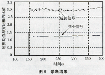 (3) Diagnostic results It can be seen from Fig. 6 that the ratio of the average velocity of the command signal to the rms is approximately 1, which is relatively close to each other; and the ratio of the average velocity of the feedback signal to the rms is approximately 3, indicating a large difference between the two. , In order to diagnose the first-class spray desuperheating valve viscous-sliding failure.
VI. CONCLUSION In connection with the actual conditions of thermal power plants, the fault diagnosis of thermal control systems was studied. The superheated steam temperature control system was taken as an example to summarize the fault types and diagnostic methods. At the same time, some simple and practical fault diagnosis methods are used in the application to diagnose common faults, and fault diagnosis process tests are performed in the field and good application results are obtained.
First, the composition of superheated steam temperature control system Superheated steam temperature control is a very important control system in the thermal control system, its main task is to maintain the superheater outlet temperature within the allowable range and protect the superheater, so that the wall temperature does not exceed Allow temperature. The temporary deviation of the superheated steam temperature must not exceed ±10°C, and the long-term deviation must not exceed ±5°C. Excessive temperatures will cause overheating of the superheater and the turbine high pressure cylinders to be damaged; lower temperatures will reduce the unit's thermal efficiency and affect economic operation [3]. The failure of the superheated steam temperature control system will bring serious consequences to the operation of the entire power plant. Therefore, the study of fault diagnosis using the superheated steam temperature control system is representative and practical.
Figure 1 shows the structure of superheated steam temperature control system for a 300MW unit in a thermal power plant. The control system adopts two-stage water injection method to reduce the temperature. The steam generated by the boiler steam drum is heated by the superheater of the ceiling and merges into a pipeline after the outlet box of the vertical low-temperature superheater. The B side enters the screen superheater. After the rear screen outlet header, the two pipes on the left and right sides are desuperheated by the secondary and secondary sprays and finally enter the final superheater [4].

According to the need of fault diagnosis of the superheated steam temperature control system, important sensors and actuators included in the superheated steam temperature control system were sorted out. Among them, the sensors include: first-order superheater front, rear left and rear right temperature sensors, and front-end superheater Left, front right, rear left and right temperature sensors, left and right temperature sensors of the final superheater, first-level temperature-reducing water flow sensors, left secondary and right secondary desuperheating water flow sensors, etc.; actuators are: primary spray Water desuperheating valve, left secondary and right secondary sprinkler desuperheating valve, primary desuperheating water stop valve.
Second, the contents of the fault diagnosis study A typical control system structure shown in Figure 2. According to the division of each part of the control system, the objects of fault diagnosis include: (1) control objects, ie equipment body; (2) control system sensors; (3) control system actuators; (4) caused by changes in the control system state Failure [5]. Because the fault diagnosis of the equipment body is studied separately, the fault diagnosis of the control system studied in this paper only includes sensor fault diagnosis, actuator fault diagnosis and operating status diagnosis.

Combined with the structural features of the superheated steam temperature control system, the research contents of fault diagnosis are summarized as follows: (1) The fault diagnosis of important sensors in the superheated steam temperature control system is studied, including monitoring whether each temperature sensor and desuperheating water flow sensor is working properly. If there is a fault, an alarm display is performed and the fault sensor is separated; (2) The fault diagnosis of important actuators in the superheated steam temperature control system is studied, including monitoring of the operation status of each spray water temperature reducing control valve and each shutoff valve, and the fault is found Alarm and separate fault actuators in time; (3) Study the diagnosis of the system fault caused by the change of state of the superheated steam temperature control system, diagnose the cause of the fault and give the operation instructions.
Third, the superheated steam temperature control system common faults 3.1 sensor fault Superheated steam temperature control system common sensor faults include: gain, deviation, overspeed, pulse fault and so on.
(1) Sensor constant gain fault can be expressed as:
Where: uin(t), uout(t) are the input and output signals of the sensor, and ai is the proportional coefficient of constant gain variation.
(2) Sensor constant deviation fault can be expressed as:
(3) Sensor disconnection fault can be expressed as:
Equation (3) shows that the sensor has no signal output.
(4) Sensor overspeed fault can be expressed as:
(5) Sensor pulse fault can be expressed as:
Where δ is the pulse signal superimposed on the sensor output signal.
3.2 Actuator faults Common actuator faults in superheated steam temperature control systems include: gain, offset, stuck, hysteresis, stick-slip, leakage fault, etc., where the description of gain and offset faults is the same as above, and other fault features are simplified. As follows.
(1) Actuator stuck failure can be expressed as:
Where ai is a constant. That is, the actuator output does not change with the input, but stabilizes at a fixed position.
(2) Hysteresis of the actuator can be expressed as:
(3) Under normal conditions, the valve stem moves smoothly, but when viscous-sliding failure occurs, the valve stem action is "motion-stop-motion" movement, which is a kind of damage to the valve. The fault phenomenon is shown in Figure 3 [6].

Q=λ(uout=0)(8)
Where: Q is the actuator-controlled flow; λ is a constant. That is, when the actuator valve is completely closed, there is still a flow signal.
Fault Diagnosis Theories and Methods Although there are many kinds of fault diagnosis theories and methods, they can be generalized into two categories [4,7]: (1) Diagnostic theories and methods based on mathematical models, such as fault detection filtering Instrumental methods, equivalent space equation methods, fault detection methods, etc.; (2) Non-model-based diagnostic theory and methods, such as multivariate statistical methods, neural network methods, expert system methods, or data analysis methods [7].
According to the author's research and combined with the characteristics of the thermal control system, the following diagnostic methods have high practical value in the fault diagnosis of the thermal control system.
(1) For some simple non-correlated faults in thermal control systems, simple, targeted methods such as signal analysis and redundancy analysis methods can be used. Although simple, these methods are easy to implement and can effectively diagnose such failures.
(2) Relatively complicated diagnostic methods need to be used for relatively complex faults that have a correlation. Because the thermal control system is not easy to establish an accurate mathematical model, it is difficult to achieve a good diagnostic effect in the application based on the mathematical model; and the statistical method does not depend on the mathematical model, it can find out in a large amount of historical real-time data Fault features and fault information are therefore a fault diagnosis method suitable for application in thermal control systems.
(3) Due to the inaccuracy of the statistical method and its own limitations, the accuracy of fault diagnosis is not high and fault separation is difficult. Therefore, it is an ideal solution to establish a comprehensive diagnosis method based on statistical methods and supplemented by mathematical model methods to achieve fault diagnosis of thermal control systems.
V. DIAGNOSIS EXAMPLE Diagnostic tests were conducted on failures, breaks, gains, deviations, overspeeds, etc., of the sensors in the superheated steam temperature control system of the thermal power plant, and failures of the actuators such as stuck, hysteresis, and stick-slip. The diagnostic methods used for troubleshooting are simple diagnostic methods for this type of failure. These methods are simple, reliable and have high diagnostic accuracy. After field testing, they have achieved good diagnostic results.
5.1 Disconnection fault of the left temperature sensor (K-type thermocouple) after the secondary superheater (1) Fault phenomenon As shown in Figure 4, the temperature signal suddenly jumps from 463.49°C to 25.45°C (thermocouple cold junction compensation temperature). The rate of change far exceeds the normal rate of change of the sensor. From the figure it is easy to see that a disconnection fault has occurred in the left temperature sensor after the secondary superheater.

(3) The diagnosis result is 463.49°C at a moment before the fault, the fault time is 25.45°C, and the diagnosis cycle is 1s. Therefore, the rate of change of the temperature signal at this moment is 438.04° C./s, which is far beyond the maximum allowable change rate of the temperature sensor, so that a breakage fault of the left temperature sensor after the secondary superheater is diagnosed at this time.
5.2 Primary spray water desuperheating valve stick-slip fault (1) Fault phenomenon It can be clearly seen from Figure 5 that the command signal changes smoothly, and the feedback signal has a step-like change, so the desuperheating valve has viscous-sliding failure produce.


VI. CONCLUSION In connection with the actual conditions of thermal power plants, the fault diagnosis of thermal control systems was studied. The superheated steam temperature control system was taken as an example to summarize the fault types and diagnostic methods. At the same time, some simple and practical fault diagnosis methods are used in the application to diagnose common faults, and fault diagnosis process tests are performed in the field and good application results are obtained.
Folding Packing Without Sealing
One of the most versatile automatic clothing folding packaging equipment, suitable for thin and thick all kinds of clothing, as well as all kinds of pants, and complete automatic folding crotch.A multi-functional intelligent automatic packing machine for T-shirts, POLO, super soft fabric garments, thin jackets, thin sweaters and other garments that have paper wrapping requirements. This machine has automatic paper feeding and automatic wrapping functions, which can meet different customized packaging requirements.
Clothes Folding Machine Price, Machine To Fold Clothes, Auto Folding Laundry Machine, Auto Folding Clothes Machine
SHENZHEN LINGCHUANG ZHUOYUE TECHNOLOGY CO., LTD , https://www.szlcautos.com