The protocol decoding function of the oscilloscope is not unfamiliar. Have you ever experienced that the waveform looks normal, the protocol parameters and decoding settings are correct, but it cannot be decoded normally? This article takes the UART protocol as an example to share the troubleshooting process caused by the baud rate drift.
What is the baud rate drift? It can be understood that the crystal of the measured component has a deviation, which causes the actual baud rate to be inconsistent with the normal baud rate. Why is the baud rate drift causing communication anomalies? This article starts with the waveform and takes your self-test decoding results.
First, the baud rate drift causes troubleshooting of communication anomalies
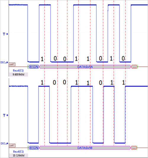
Leading to such a real example, the serial port data sent by the PC is "0xEE 0x61 0x32 0xFF 0xFC 0xFF 0xFF", and the oscilloscope decoding result is "0xEE 0x98 0xF6 0xFC 0xFF" to initially determine the communication failure. However, the protocol parameter setting and decoding settings are correct. Why is there a problem of inconsistent transmission and reception? In the following, the baud rate in the protocol parameter setting during decoding is set to 9600 bps, the actual 9600 bps, 10126 bps waveform decoding results comparison (as shown in Figure 1) analysis as an example, sharing the baud rate drift results in a waveform There is a deviation, and thus the cause of the communication abnormality is investigated.

Figure 1 Different waveform decoding results at the same decoding baud rate
First talk about the decoding principle of UART. When the oscilloscope decodes the UART signal, the falling edge after the idle level is used as the start bit, and then the samples are equally spaced from the waveform, and most of the samples in the equally spaced time segments are used as the decoded value of the bit. Waveforms with different baud rates, the minimum data bit width is inconsistent, time T=1/sampling rate, the time corresponding to the waveform with large actual sampling rate is small, so the waveform with the baud rate of 10126 bps can be seen from Figure 1. Left shifted. When the baud rate set during decoding is 9600, the position of the sampling point is determined according to the baud rate of 9600. When the actual sampling rate is deviated from 9600 bps, the error will gradually accumulate, resulting in deviation of decoding. The larger the data bit width is set, the easier it is to superimpose the error.
Second, self-test baud rate method
Starting from the waveform, the baud rate is estimated based on the minimum bit width of the waveform. This method is suitable when the baud rate deviation is large or the baud rate is not determined. This is a self-test method that engineers are more accustomed to. To estimate the baud rate, you need to look at the minimum bit width in the waveform. As you can see from Figure 2, the time base gear is 100us, and the minimum bit width is just one grid. The minimum bit width is about 100us, which is equal to 10000bps after conversion. To get a more accurate baud rate value, you can use the oscilloscope's measurement function. Open the measure in the oscilloscope panel, select the baud rate measurement item, and observe the comparison of the baud rate measurement results, as shown in the red box in Figure 2.
The example cited at the beginning is because the baud rate has drifted, actually 10000 bps, and the decoding is set according to the normal component of 9600 bps. Therefore, the baud rate error is greater than 4%, so the decoding result will not be correct. After changing the crystal to decode, the communication is normal.

Figure 2 Estimating the baud rate from the minimum bit width of the waveform
to sum up
Although the baud rate is only a parameter in decoding, the effect of drift can not be ignored, it may be the cause of communication failure. Be careful to check the baud rate before decoding. Such a small detail may save you the time to troubleshoot in the future. From the waveform, re-examine the value of the oscilloscope. It is used to observe the waveform and analyze the data in order to detect whether the measured component is normal.
Metal 3D Printer,Ceramic Sand Casting Molds,Advanced Metal 3D Printer,Compact Binder Jet 3D Printer
Guangdong Fenghua Zhuoli Technology Co., Ltd , https://www.fhzl3d-print.com