Abstract : The TMS320F2812 DSP chip is used as the control unit. Without any gated device control, the DSP2812 software resources are used to achieve equal precision measurement. According to the number of high-frequency standard pulses in each gate time and the number of known signals, the frequency of the signal under test is obtained, and the final result is obtained through multiple times of averaging.
With the rapid development of microelectronics and computer technology, various electronic measuring instruments have undergone tremendous changes in terms of principle, function, precision, and automation level. Especially after the birth of DSP technology, electronic measurement technology has taken a step forward. A new era. In recent years, DSP has gradually become the basic device of various electronic devices, and has gradually become the most promising sunrise industry in the 21st century, and is even hailed as the revolutionary flag bearer of the digitalized era. In electronic measurement technology, frequency is one of the most basic parameters, and it has a very close relationship with many electrical parameters and non-electricity measurements. For example, many sensors measure some of the non-electrical energy into frequency, so the frequency measurement becomes even more important. A digital frequency meter is an instrument that digitally displays the frequency of the signal to be measured. The signal to be measured can be a sine wave, a square wave, or other periodically changing signal.
Digital frequency meters widely use high-speed integrated circuits and large-scale integrated circuits, making the instrument smaller, less power-consuming, and more accurate and reliable. The traditional frequency meter measurement error is relatively large, the scope is also relatively narrow, so gradually replaced by a new digital frequency meter. DSP-based equal-precision frequency meter will be widely used due to its advantages of accurate measurement, high accuracy, convenience, and low price.
We designed a simple digital frequency meter to achieve equal-accuracy frequency measurement within a wide range without any gated device control. The maximum relative error of the square wave measured in the range of 0.5 Hz to 10 MHz is less than 2e-6. The maximum relative error of the measured sine wave is less than 3.5e-5; the result is displayed on the computer via RS232 communication, which makes it easy to monitor the data.
The overall design of the program describes the traditional equal-precision frequency measurement method uses a gating device to generate a gating signal, so as to achieve synchronization between the actual gate signal and the measured signal, and to eliminate the error of a pulse generated by counting the measured signal. 1 shows.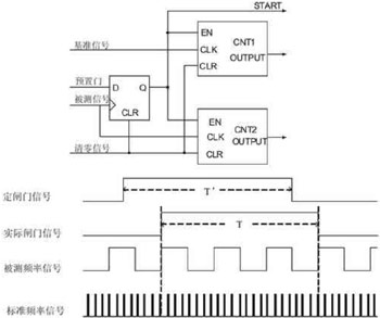
Fig. 1 The principle of traditional equal precision measurement By hardware control gate count time, when the pre-set signal (ie fixed gate signal) is high, the reference signal counter CNT1 and the measured signal counter CNT2 do not start, but wait for the rising edge of the signal to be measured Counting starts at the same time; when the presets signal is low, the two counters do not immediately shut down, and the same waits until the rising edge of the measured signal comes and then closes; therefore, the actual gate time is the integer of the cycle of the signal being measured. Times, thus achieving synchronization of the gate and the measured signal. However, the actual gate time is not fixed and depends on the frequency of the signal being measured. In addition, whether it is the use of counters or single-chip microcomputer, it is always indispensable for the gating device to achieve such accuracy measurements.
This design is based on DSP's rich software resources. After judgment and processing, it has completed equal precision measurement of the frequency of the signal under test. No gating device is required on the hardware, simplifying the circuit. System block diagram shown in Figure 2, the signal processing part of the TMS320F2812DSP chip as the core of control and measurement; signal conditioning part is mainly to complete the signal amplification, shaping and limiting; standard frequency signal generated by the 30MHz active crystal, as high frequency Standard fill pulse; Through SCI module of DSP realizes communication with upper computer, the result is shown on the upper computer.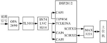
Figure 2 System Block Diagram Frequency/period measurement In the measurement of the frequency and period of the signal to be measured, equal accuracy measurement is based on the transition of the output level of the T1PWM pin when the DSP compares and matches as the opening and closing of the gate signal, since the comparison match occurs in the measured The rising edge of the signal, thus achieving the synchronization of the gate time and the measured signal. The schematic is shown in Figure 3. 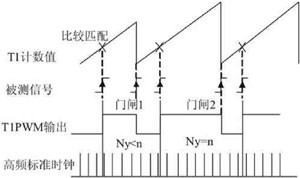
Figure 3 the principle of this frequency measurement accuracy The general-purpose timer T1 clock input selects the external timer clock. Here, the signal after conditioning is used as the clock input to the timer T1. The timer T2 clock input selects the internal CPU clock to generate the high-frequency standard fill pulse. When a general-purpose timer T1 in the F2812 on-chip EVA occurs a compare match event, the output signal of the comparison output pin T1CMP will automatically change the level state to generate a PWM wave. The capture unit CAP1 is set to capture on the rising edge, the rising edge of the PWM wave output by T1PWM is captured by CAP1, the count value of timer T2 is read at this time, and the count value of timer T2 is read again at the next comparison match. Through the two subtractions of the T2CNT value, the number of standard fill pulses during the gate time can be obtained, and then the frequency of the signal to be measured is obtained.
The transition of the T1PWM pin output level based on the comparison match of the DSP is used as the opening and closing of the gate signal, and the comparison match occurs at the rising edge of the measured signal, thereby realizing the synchronization of the gate gate time and the measured signal. The rising edges of the PWM waves generated by the two adjacent comparison matches serve as the opening and closing signals of the gate signals, respectively. The number of signals to be measured is an integer and is arbitrarily set by us. The timer T2 clock input selects the internal CPU clock that is used to generate the standard fill pulse. Set the capture unit CAP1 to capture on the rising edge, read the value in the stack CAPFIFO when it captures the rising edge, read the value in the stack on the next capture, calculate the number of standard fill pulses Ny, ensure Ny If the number is not less than a certain value, the gate time can be guaranteed to be greater than a certain value. Suppose now that the total number of high-frequency filling pulses in one gate time is not less than n. When Ny>n, the timer T1 timing cycle is increased, that is, the timer T1 period register TIPR is increased. Formula T1PR+1=n/Ny exists because n/Ny is not necessarily an integer, but a
The basic principle of cycle measurement and frequency measurement is exactly the same, the signal frequency is measured, and the cycle of the signal to be measured can be obtained according to the common T=1/f.
The start and stop time of the error analysis timer T1 is triggered by the rising edge of the signal. There is no error in the count of the measured signal within one measurement time; during this time, the number of counts of standard frequency pulses is Ny, and the difference is at most One pulse, so the theoretical error is:
|d|≤1/Ny
Obviously, the measurement accuracy is only related to Ny. As long as the Ny value is large enough, the accuracy can be guaranteed.
The hardware design is shown in Figure 4. The signal to be measured is amplified by the high-speed op amp OPA2690. After being shaped by the high-speed comparator TL3016, the edge of the output waveform is severe when the comparator is shaping the low-frequency sine wave signal. Jitter affects the measurement. The solution is to add positive feedback to the comparator to accelerate the edge of the signal and form a hysteresis at the same time, which can effectively eliminate the jitter. The shaped signal is clipped and further shaped by the high-speed Schmidt trigger SN74LVC1G14. The measurement part mainly uses the clock input pin TCLKINA of the timer T1 on the DSP2812 chip, the comparison output pin T1PWM of the timer T1, and the input pin CAP1 of the capture unit CAP1 to complete the frequency measurement. The communication part selects the MAX3221 as an RS-232 level-shifting device and performs serial communication with the host computer through a 9-pin standard RS-232 port. DSP's serial communication transmit pin SCIRXD and serial communication receive pin SCITXD are mainly used.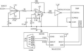
Figure 4 hardware circuit connection diagram The software design software design section mainly includes the following four parts:
• Initialization: Configuration of variable parameters, system clock, PIE, EV, Flash, GPIO, etc.
• Interrupt module: SCI interrupt and timer T2, T3 overflow interrupt.
Data processing module: segment + take arithmetic mean.
Output operation module: Data is transmitted to the host computer via RS-232.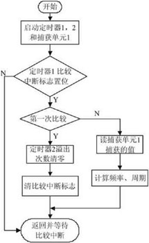
Figure 5 shows the frequency and cycle software flow chart, and Figure 6 shows the timer 2 overflow interrupt flow chart.
Figure 5 Frequency and cycle diagram
Figure 6 Timer T2 overflow interrupt flow chart When this part is initialized, the following configuration is needed: General-purpose timer T1 clock input is external timer clock, general-purpose timer T2 clock input is internal clock input, used to count standard pulses, the standard pulse is from external 30MHz The source oscillator provides; Capture unit 1 is set to capture on rising edge to capture the rising edge of the T1PWM pin output PWM wave and read the timer T2 count value T2CNT at each compare match. This value is stored in the CAP1FIFO. The FIFO stack state in the status register of the capture unit 1 is set to an empty stack at the time of initialization; the timer period of the timer T1 is set to the cycle length of the four measured signals, and passes through a measured period of the timer T1 in a timing period. The number of standard pulses, the frequency of the measured signal is calculated, and then the measured signal is segmented into the low frequency band (less than 46.875Hz), the middle frequency band (more than 46.875Hz, less than 2343.75KHz), and the high frequency band (greater than 2343.75KHz), where the segmentation is based on the count saturation value of the timer 65536 and the number of counts should be greater than or equal to 1. If the signal frequency is in the medium-high frequency band, the timer T1 and timer T2 registers are reconfigured to change the timing period and the number of high-frequency filling pulses in each gate time. The frequency and period are calculated in the next timing cycle of timer T1. In addition, the number of overflows of the timer T2 is cleared at the first occurrence of the comparison match, and whether or not the comparison match occurs for the first time is determined by setting a flag. The number of overflows is not counted until after the number of overflows is cleared, until the second compare match occurs.
Next Steps for Improvement Opinions The measurement error of this method mainly comes from the hardware part. The quality of the shaping circuit is directly related to the level of measurement accuracy. Therefore, our next step is to improve the shaping effect and anti-jamming performance of the shaping circuit, and to minimize the error caused by signal shaping.
Since the DSP timer has count saturation when counting, there is an upper limit in achieving such accuracy measurement. That is, when the frequency of the measured signal is higher than the frequency of the high-frequency filling pulse, the method cannot achieve equal accuracy. Based on this scheme, the following processing can be performed: Select the timer T1 fixed number of signals within the timing period, set T1PR to 65529, and modify the timer T2 clock to 75MHz, so that each door can be guaranteed The number of high frequency fill pulses during the gate time ensures accuracy when frequency and period measurements of high frequency signals are performed.
However, when the timer T1 clock input is selected as an external clock, there is a limit to the input range of the signal under test. If the range of the signal to be measured is further increased to achieve a range of over 100 megahertz or upper Ghertz, the phase measurement method may be considered. The measured signal is set to 360 degrees, and the measured signal frequency is calculated according to the phase difference between the measured signal and the standard signal.
With the rapid development of microelectronics and computer technology, various electronic measuring instruments have undergone tremendous changes in terms of principle, function, precision, and automation level. Especially after the birth of DSP technology, electronic measurement technology has taken a step forward. A new era. In recent years, DSP has gradually become the basic device of various electronic devices, and has gradually become the most promising sunrise industry in the 21st century, and is even hailed as the revolutionary flag bearer of the digitalized era. In electronic measurement technology, frequency is one of the most basic parameters, and it has a very close relationship with many electrical parameters and non-electricity measurements. For example, many sensors measure some of the non-electrical energy into frequency, so the frequency measurement becomes even more important. A digital frequency meter is an instrument that digitally displays the frequency of the signal to be measured. The signal to be measured can be a sine wave, a square wave, or other periodically changing signal.
Digital frequency meters widely use high-speed integrated circuits and large-scale integrated circuits, making the instrument smaller, less power-consuming, and more accurate and reliable. The traditional frequency meter measurement error is relatively large, the scope is also relatively narrow, so gradually replaced by a new digital frequency meter. DSP-based equal-precision frequency meter will be widely used due to its advantages of accurate measurement, high accuracy, convenience, and low price.
We designed a simple digital frequency meter to achieve equal-accuracy frequency measurement within a wide range without any gated device control. The maximum relative error of the square wave measured in the range of 0.5 Hz to 10 MHz is less than 2e-6. The maximum relative error of the measured sine wave is less than 3.5e-5; the result is displayed on the computer via RS232 communication, which makes it easy to monitor the data.
The overall design of the program describes the traditional equal-precision frequency measurement method uses a gating device to generate a gating signal, so as to achieve synchronization between the actual gate signal and the measured signal, and to eliminate the error of a pulse generated by counting the measured signal. 1 shows.

Fig. 1 The principle of traditional equal precision measurement
This design is based on DSP's rich software resources. After judgment and processing, it has completed equal precision measurement of the frequency of the signal under test. No gating device is required on the hardware, simplifying the circuit. System block diagram shown in Figure 2, the signal processing part of the TMS320F2812DSP chip as the core of control and measurement; signal conditioning part is mainly to complete the signal amplification, shaping and limiting; standard frequency signal generated by the 30MHz active crystal, as high frequency Standard fill pulse; Through SCI module of DSP realizes communication with upper computer, the result is shown on the upper computer.

Figure 2 System Block Diagram

Figure 3 the principle of this frequency measurement accuracy
The transition of the T1PWM pin output level based on the comparison match of the DSP is used as the opening and closing of the gate signal, and the comparison match occurs at the rising edge of the measured signal, thereby realizing the synchronization of the gate gate time and the measured signal. The rising edges of the PWM waves generated by the two adjacent comparison matches serve as the opening and closing signals of the gate signals, respectively. The number of signals to be measured is an integer and is arbitrarily set by us. The timer T2 clock input selects the internal CPU clock that is used to generate the standard fill pulse. Set the capture unit CAP1 to capture on the rising edge, read the value in the stack CAPFIFO when it captures the rising edge, read the value in the stack on the next capture, calculate the number of standard fill pulses Ny, ensure Ny If the number is not less than a certain value, the gate time can be guaranteed to be greater than a certain value. Suppose now that the total number of high-frequency filling pulses in one gate time is not less than n. When Ny>n, the timer T1 timing cycle is increased, that is, the timer T1 period register TIPR is increased. Formula T1PR+1=n/Ny exists because n/Ny is not necessarily an integer, but a
The basic principle of cycle measurement and frequency measurement is exactly the same, the signal frequency is measured, and the cycle of the signal to be measured can be obtained according to the common T=1/f.
The start and stop time of the error analysis timer T1 is triggered by the rising edge of the signal. There is no error in the count of the measured signal within one measurement time; during this time, the number of counts of standard frequency pulses is Ny, and the difference is at most One pulse, so the theoretical error is:
|d|≤1/Ny
Obviously, the measurement accuracy is only related to Ny. As long as the Ny value is large enough, the accuracy can be guaranteed.
The hardware design is shown in Figure 4. The signal to be measured is amplified by the high-speed op amp OPA2690. After being shaped by the high-speed comparator TL3016, the edge of the output waveform is severe when the comparator is shaping the low-frequency sine wave signal. Jitter affects the measurement. The solution is to add positive feedback to the comparator to accelerate the edge of the signal and form a hysteresis at the same time, which can effectively eliminate the jitter. The shaped signal is clipped and further shaped by the high-speed Schmidt trigger SN74LVC1G14. The measurement part mainly uses the clock input pin TCLKINA of the timer T1 on the DSP2812 chip, the comparison output pin T1PWM of the timer T1, and the input pin CAP1 of the capture unit CAP1 to complete the frequency measurement. The communication part selects the MAX3221 as an RS-232 level-shifting device and performs serial communication with the host computer through a 9-pin standard RS-232 port. DSP's serial communication transmit pin SCIRXD and serial communication receive pin SCITXD are mainly used.

Figure 4 hardware circuit connection diagram
• Initialization: Configuration of variable parameters, system clock, PIE, EV, Flash, GPIO, etc.
• Interrupt module: SCI interrupt and timer T2, T3 overflow interrupt.
Data processing module: segment + take arithmetic mean.
Output operation module: Data is transmitted to the host computer via RS-232.

Figure 5 shows the frequency and cycle software flow chart, and Figure 6 shows the timer 2 overflow interrupt flow chart.
Figure 5 Frequency and cycle diagram

Figure 6 Timer T2 overflow interrupt flow chart
Next Steps for Improvement Opinions The measurement error of this method mainly comes from the hardware part. The quality of the shaping circuit is directly related to the level of measurement accuracy. Therefore, our next step is to improve the shaping effect and anti-jamming performance of the shaping circuit, and to minimize the error caused by signal shaping.
Since the DSP timer has count saturation when counting, there is an upper limit in achieving such accuracy measurement. That is, when the frequency of the measured signal is higher than the frequency of the high-frequency filling pulse, the method cannot achieve equal accuracy. Based on this scheme, the following processing can be performed: Select the timer T1 fixed number of signals within the timing period, set T1PR to 65529, and modify the timer T2 clock to 75MHz, so that each door can be guaranteed The number of high frequency fill pulses during the gate time ensures accuracy when frequency and period measurements of high frequency signals are performed.
However, when the timer T1 clock input is selected as an external clock, there is a limit to the input range of the signal under test. If the range of the signal to be measured is further increased to achieve a range of over 100 megahertz or upper Ghertz, the phase measurement method may be considered. The measured signal is set to 360 degrees, and the measured signal frequency is calculated according to the phase difference between the measured signal and the standard signal.
Disposable FFP2 Particulate Respirator
Disposable Mask,Disposable Folded Mask,FFP2 Disposable Face Mask,Disposable FFP2 Particulate Respirator
Henan Aklly Filter Engineering Co., Ltd , https://www.akllyfilte.com